#058 Three-Speed Concentric Shaft Gear Transmission – 507 Mechanical Movements 3D Animation

#058 Three-Speed Concentric Shaft Gear Transmission – 507 Mechanical Movements 3D Animation

Monday, Apr 6, 2026

Movement No. 58 presents a highly ingenious multi-speed transmission system that delivers three distinct output speeds to a lower shaft using a clever arrangement of concentric hollow shafts, multiple pulleys, and spur gears of different sizes — all selectable by shifting a single drive belt. The input side consists of four pulleys mounted side by side. The first is a loose idler pulley — when the belt rides here, no motion is transmitted at all, giving a neutral state. The second pulley is fixed directly to the solid main shaft, which carries a small spur gear on its opposite end. The third pulley is fixed to a hollow shaft that runs concentrically over the main shaft — independent of it — and carries a second, larger spur gear on its other end. The fourth pulley is fixed to yet another hollow shaft that runs concentrically over the previous hollow shaft, also independent, carrying an even larger spur gear at its other end. All three spur gears of different sizes mesh with a common gear on the lower output shaft. When the belt is placed on pulley two, the main shaft and its small spur gear are driven — producing the highest output speed on the lower shaft due to the small gear ratio. When shifted to pulley three, the first hollow shaft and its medium spur gear are driven — producing an intermediate output speed. When shifted to pulley four, the outer hollow shaft and its large spur gear are driven — producing the lowest output speed with the highest torque. This elegant system of nested concentric shafts allows three completely independent speed ratios to be selected by a single belt shift, without requiring any gear-shifting mechanism — a remarkable feat of compact mechanical design used in machine tools and early industrial equipment.

@
2 minute read
#057 Belt-Driven Concentric Gears with Planetary Pinion – 507 Mechanical Movements 3D Animation

#057 Belt-Driven Concentric Gears with Planetary Pinion – 507 Mechanical Movements 3D Animation

Sunday, Apr 5, 2026

Movement No. 57 presents one of the most mechanically complex and visually spectacular mechanisms in the early sections of the 507 collection — a belt-driven system of two concentric gears driving an intermediate planetary pinion in a compound orbital motion. The driver is a small pulley at the top, which sends drive to the system via two belts or bands. These bands connect to the large internally-toothed ring gear and to a smaller concentric spur gear positioned inside it — both centered on the same axis. Crucially, the two bands are arranged so that the ring gear and the inner concentric gear are driven in opposite directions simultaneously — one clockwise and the other counterclockwise — by the single driving pulley. Between these two counter-rotating concentric gears sits an intermediate pinion at the bottom, meshing with both the inner surface of the ring gear and the outer surface of the inner concentric gear simultaneously. Because the two gears surrounding this pinion rotate in opposite directions, the pinion is driven to rotate about its own center axis — spinning on its own. But because the pinion is constrained between the two concentric gears and both are rotating, the pinion also undergoes orbital motion — revolving around the common center of the two concentric gears. The result is a compound planetary motion: the pinion simultaneously spins on its own axis and orbits around the central axis — a motion with characteristics directly related to early epicyclic and planetary gear theory. This combination of belt drive, internal gearing, and planetary motion makes Movement No. 57 one of the most intellectually rich mechanisms in the entire collection.

@
2 minute read
#056 Eccentric Slot Lever Back Gear – 507 Mechanical Movements 3D Animation

#056 Eccentric Slot Lever Back Gear – 507 Mechanical Movements 3D Animation

Saturday, Apr 4, 2026

Movement No. 56 presents a clever and compact mechanism used specifically for engaging and disengaging the back gear on lathes — a device that allows the lathe operator to select between high-speed direct drive and low-speed high-torque back-gear drive without dismantling anything. The mechanism works through the ingenious use of an eccentrically cut slot in a lever. The large wheel’s shaft does not run in a fixed bearing — instead, it slides within a slot that is cut into the lever arm. The critical geometric detail is that this slot is cut eccentrically relative to the lever’s pivot point or fulcrum: the slot’s centerline does not pass through the fulcrum, but is offset from it. When the lever is in its raised position, the eccentric slot geometry positions the large wheel’s shaft forward — bringing the large wheel into mesh with its mating gear and engaging the back gear drive. When the operator depresses the lever downward, the eccentric slot — being offset from the fulcrum — causes the shaft to be drawn backward as the lever rotates about its pivot. This backward movement of the shaft pulls the large wheel away from its mating gear, disengaging the back gear entirely. The elegance of this design lies in the fact that a simple lever depression simultaneously moves the shaft backward through the cam-like action of the eccentric slot, combining the functions of a cam mechanism and a lever into a single compact component. This mechanism was an essential feature of 19th-century metal-cutting lathes, enabling operators to quickly switch between high spindle speeds for light finishing cuts and low spindle speeds with high torque for heavy roughing cuts on large-diameter workpieces.

@
2 minute read
#055 Differential Speed Gears on Same Shaft – 507 Mechanical Movements 3D Animation

#055 Differential Speed Gears on Same Shaft – 507 Mechanical Movements 3D Animation

Friday, Apr 3, 2026

Movement No. 55 presents a deceptively simple yet conceptually rich gear arrangement: a single pinion B simultaneously driving two gears, A and C, which are mounted on the same shaft — but rotating at different speeds relative to each other. At first glance, this seems paradoxical — how can two gears on the same shaft rotate at different speeds? The answer lies in the fact that gears A and C are of different diameters and different tooth counts, while both mesh with the same driving pinion B. Because the speed ratio between a gear and its driving pinion is determined by the ratio of their tooth counts, gear A — having a different number of teeth from gear C — will be driven at a different angular velocity than gear C, even though the same pinion B drives both simultaneously. For this to work, gears A and C must be mounted loosely on the shared shaft — free to rotate independently — rather than being keyed to it. The shaft itself may then be driven by one of the gears through a selective clutch or other mechanism, or the arrangement may serve as the basis for a differential or compound gear train. This mechanism elegantly demonstrates that two gears can coexist on the same shaft axis while rotating at entirely different speeds, and that a single pinion can serve as the simultaneous driver for multiple gears of different ratios. This principle is fundamental to the design of compound gear trains, back-gear mechanisms in lathes, and multi-speed transmission stages found throughout mechanical engineering.

@
2 minute read
#054 Mangle Star Wheel – 507 Mechanical Movements 3D Animation

#054 Mangle Star Wheel – 507 Mechanical Movements 3D Animation

Wednesday, Apr 1, 2026

Movement No. 54 presents the Mangle Wheel in its star-wheel form — a mechanism designed to produce alternating rotary motion from a continuous unidirectional input. While Movement No. 36 introduced the classic mangle wheel with a pinion traveling inside and outside a continuous tooth track, Movement No. 54 presents a related but distinct variation: the star wheel configuration. The star wheel is a gear wheel with teeth or projections arranged around its periphery in a star-like pattern, combined with a driving element that engages these projections in sequence. The key characteristic shared with the mangle wheel family is the ability to produce reciprocating — back-and-forth — rotary output from a continuously rotating input, without requiring the input to reverse its direction. As the driving element rotates continuously in one direction, it engages the star wheel’s projections alternately on one side then the other, pushing the star wheel first in one rotational direction, then reversing it — creating the characteristic alternating rotary motion. This type of mechanism was historically used in mangle machines for pressing and wringing laundry, where the rollers needed to reverse direction periodically to feed the fabric back and forth. The alternating output is also useful in winding mechanisms, textile machinery, and any application where a periodic reversal of rotational direction is required from a continuously running prime mover. The star wheel’s simple, robust geometry makes it well suited for transmitting significant force while producing this alternating motion reliably and repeatedly.

@
2 minute read
#053 Double Clutch Bevel Gear Reverser – 507 Mechanical Movements 3D Animation

#053 Double Clutch Bevel Gear Reverser – 507 Mechanical Movements 3D Animation

Tuesday, Mar 31, 2026

Movement No. 53 presents an elegant and compact reversing mechanism that allows a single continuously rotating vertical shaft to drive a horizontal output shaft in either direction — forward or reverse — by means of a double clutch and bevel gear arrangement. The system is built around a central bevel gear on the vertical shaft that simultaneously meshes with two bevel gears mounted on the horizontal shaft. Because these two horizontal bevel gears are on opposite sides of the vertical shaft’s driving gear, they are driven in opposite directions to each other at all times — one spins clockwise while the other spins counterclockwise, continuously and simultaneously. However, both horizontal bevel gears are mounted loosely on the horizontal shaft — they spin freely without driving the shaft, as long as the clutch is disengaged. Between these two loose bevel gears sits the double clutch — a sliding element mounted on a key or feather fixed in the horizontal shaft, so it is rotationally locked to the shaft but free to slide axially. When the double clutch is slid to one side, it engages with one of the loose bevel gears and locks it to the horizontal shaft — the shaft then rotates in the direction that gear is spinning. When slid to the opposite side, it engages with the other bevel gear — now driving the shaft in the opposite direction. In the center neutral position, both bevel gears spin freely and the horizontal shaft remains stationary. This mechanism provides three states — forward, neutral, and reverse — from a single continuously running input, making it highly practical for machine tools, mills, and any industrial equipment requiring reversible output without stopping or reversing the prime mover.

@
2 minute read
#052 Stud and Hole Clutch – 507 Mechanical Movements 3D Animation

#052 Stud and Hole Clutch – 507 Mechanical Movements 3D Animation

Monday, Mar 30, 2026

Movement No. 52 presents yet another variation of the clutch-box — a simple yet effective positive engagement clutch that uses protruding studs and corresponding holes to lock two rotating disk-wheels together as a single unit. The mechanism consists of two disk-wheels mounted on the same shaft axis, facing each other. One disk carries a set of studs — cylindrical pins projecting axially from its face. The other disk has a matching set of holes positioned at exactly the same radial distance and angular spacing as the studs on the first disk. When the two disks are pressed axially together, the studs on the first disk enter and seat into the holes of the second disk. Once engaged, the studs physically interlock with the holes, creating a rigid positive connection — the two disks are now mechanically locked together and rotate as one, transmitting full torque between them with no slippage whatsoever. When the disks are pulled apart axially, the studs withdraw from the holes and the two disks are free to rotate independently. Compared to the frictional clutch-box of Movement No. 47 and the jaw clutch of Movement No. 48, the stud-and-hole clutch of No. 52 offers a particularly simple and clean positive engagement mechanism — the circular studs and round holes are easy to manufacture with high precision, and the engagement is self-centering as the tapered or rounded stud tips guide themselves into the holes. Like all positive engagement clutches, this design must be engaged carefully when both disks are at the same rotational speed, as engaging under speed mismatch would cause the studs to strike the face of the opposing disk rather than entering the holes cleanly.

@
2 minute read
#051 Universal Joint – 507 Mechanical Movements 3D Animation

#051 Universal Joint – 507 Mechanical Movements 3D Animation

Sunday, Mar 29, 2026

Movement No. 51 presents the first of two universal joint designs — one of the most mechanically important and widely used shaft coupling mechanisms in engineering history. A universal joint, also known as a Hooke’s joint or Cardan joint, solves a fundamental problem in mechanical power transmission: how to transmit continuous rotary motion between two shafts whose axes are not collinear — that is, two shafts that meet at an angle rather than being perfectly aligned. In a simple rigid coupling, any angular misalignment between two shafts would cause binding, vibration, and rapid mechanical failure. The universal joint elegantly solves this by introducing a cross-shaped intermediate element — the spider or cross piece — with four trunnions projecting at right angles. Two opposite trunnions pivot in a yoke fixed to the first shaft, while the other two trunnions pivot in a yoke fixed to the second shaft. This cruciform arrangement allows the joint to flex through a range of angles while continuously transmitting rotation from one shaft to the other. However, the classic single Hooke’s joint has a well-known kinematic limitation: even when the input shaft rotates at perfectly constant speed, the output shaft experiences a cyclic variation in angular velocity — speeding up and slowing down twice per revolution — whenever the shafts are at an angle. The magnitude of this velocity variation increases with the joint angle. This property makes the single universal joint unsuitable for applications requiring smooth, constant-velocity output at significant joint angles — a limitation addressed by using two joints in series, as in automotive driveshafts. Universal joints are found today in automobile driveshafts, steering columns, industrial machinery, and wherever angular shaft misalignment must be accommodated in a rotating drive system.

@
2 minute read
#050 Universal Joint – 507 Mechanical Movements 3D Animation

#050 Universal Joint – 507 Mechanical Movements 3D Animation

Saturday, Mar 28, 2026

Movement No. 50 presents the first of two universal joint designs — one of the most mechanically important and widely used shaft coupling mechanisms in engineering history. A universal joint, also known as a Hooke’s joint or Cardan joint, solves a fundamental problem in mechanical power transmission: how to transmit continuous rotary motion between two shafts whose axes are not collinear — that is, two shafts that meet at an angle rather than being perfectly aligned. In a simple rigid coupling, any angular misalignment between two shafts would cause binding, vibration, and rapid mechanical failure. The universal joint elegantly solves this by introducing a cross-shaped intermediate element — the spider or cross piece — with four trunnions projecting at right angles. Two opposite trunnions pivot in a yoke fixed to the first shaft, while the other two trunnions pivot in a yoke fixed to the second shaft. This cruciform arrangement allows the joint to flex through a range of angles while continuously transmitting rotation from one shaft to the other. However, the classic single Hooke’s joint has a well-known kinematic limitation: even when the input shaft rotates at perfectly constant speed, the output shaft experiences a cyclic variation in angular velocity — speeding up and slowing down twice per revolution — whenever the shafts are at an angle. The magnitude of this velocity variation increases with the joint angle. This property makes the single universal joint unsuitable for applications requiring smooth, constant-velocity output at significant joint angles — a limitation addressed by using two joints in series, as in automotive driveshafts. Universal joints are found today in automobile driveshafts, steering columns, industrial machinery, and wherever angular shaft misalignment must be accommodated in a rotating drive system.

@
2 minute read
#049 Ratchet and Bevel Gear – 507 Mechanical Movements 3D Animation

#049 Ratchet and Bevel Gear – 507 Mechanical Movements 3D Animation

Thursday, Mar 26, 2026

Movement No. 49 presents a remarkably clever mechanism that converts alternating oscillating circular motion of a horizontal shaft into continuous one-directional rotary motion of a vertical shaft — using a dual ratchet and bevel gear arrangement. Two bevel gears are mounted loosely on the horizontal shaft, each with a ratchet wheel rigidly attached. The ratchet teeth on the two wheels are oriented in opposite directions — one allows clockwise rotation and locks counterclockwise, the other does the reverse. The pawls are fixed to arms rigidly secured to the horizontal shaft itself. As the horizontal shaft oscillates back and forth, the pawls alternately engage each ratchet wheel in sequence. During one half of the oscillation, one pawl drives its bevel gear forward, transmitting rotation to the vertical output shaft — while the other pawl simply skips freely over its ratchet teeth. On the return stroke, the roles reverse: the second bevel gear is driven while the first freewheels. In this way, both the forward and return strokes of the oscillating input contribute useful driving force to the vertical shaft, which rotates continuously in one direction throughout the full cycle. This elegant mechanism demonstrates how a pair of opposing ratchets can rectify an oscillating input into smooth, continuous unidirectional output — a principle that appears in hand drills, winches, clockwork mechanisms, and early industrial machinery wherever reciprocating motion must be converted to continuous rotation.

@
2 minute read

© 2026 Formline 3D Mechanisms

Powered by Formline 3D

Formline 3D

Formline 3D is a 3D animation channel exploring the form, structure, and design of the world around us.

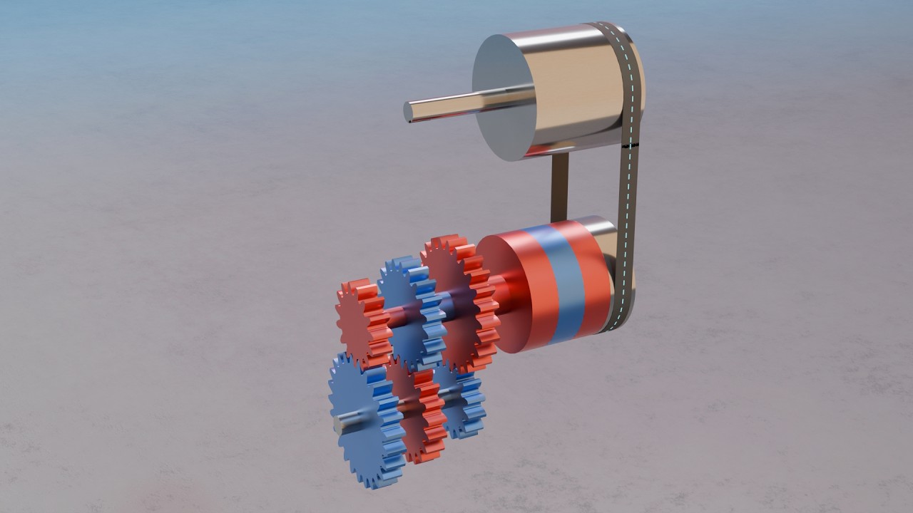
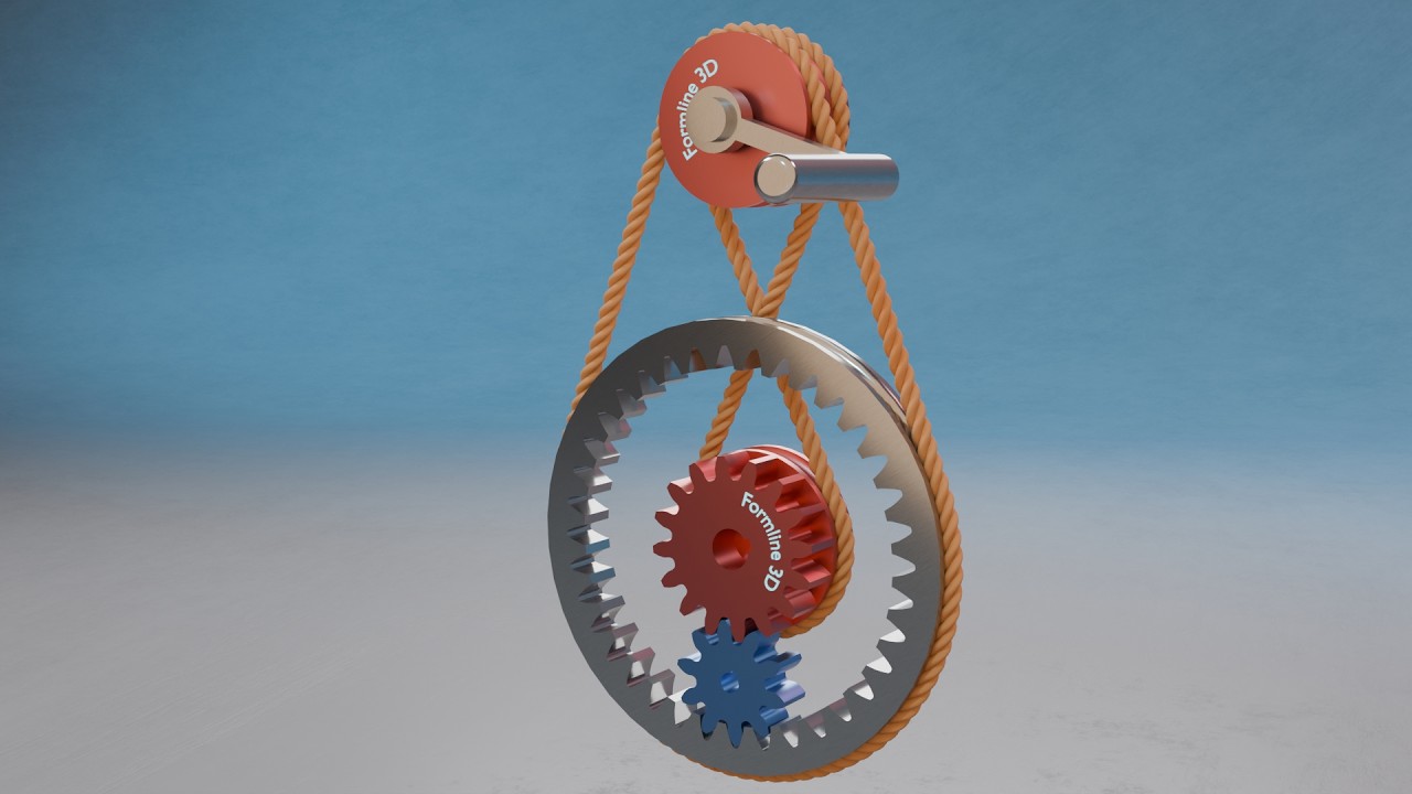
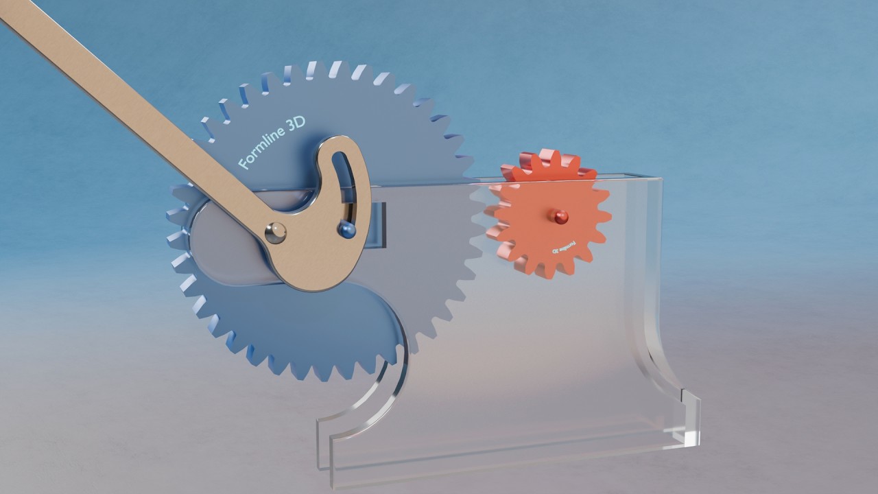
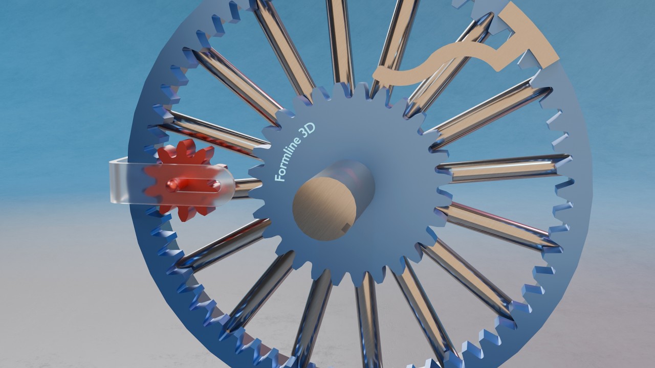
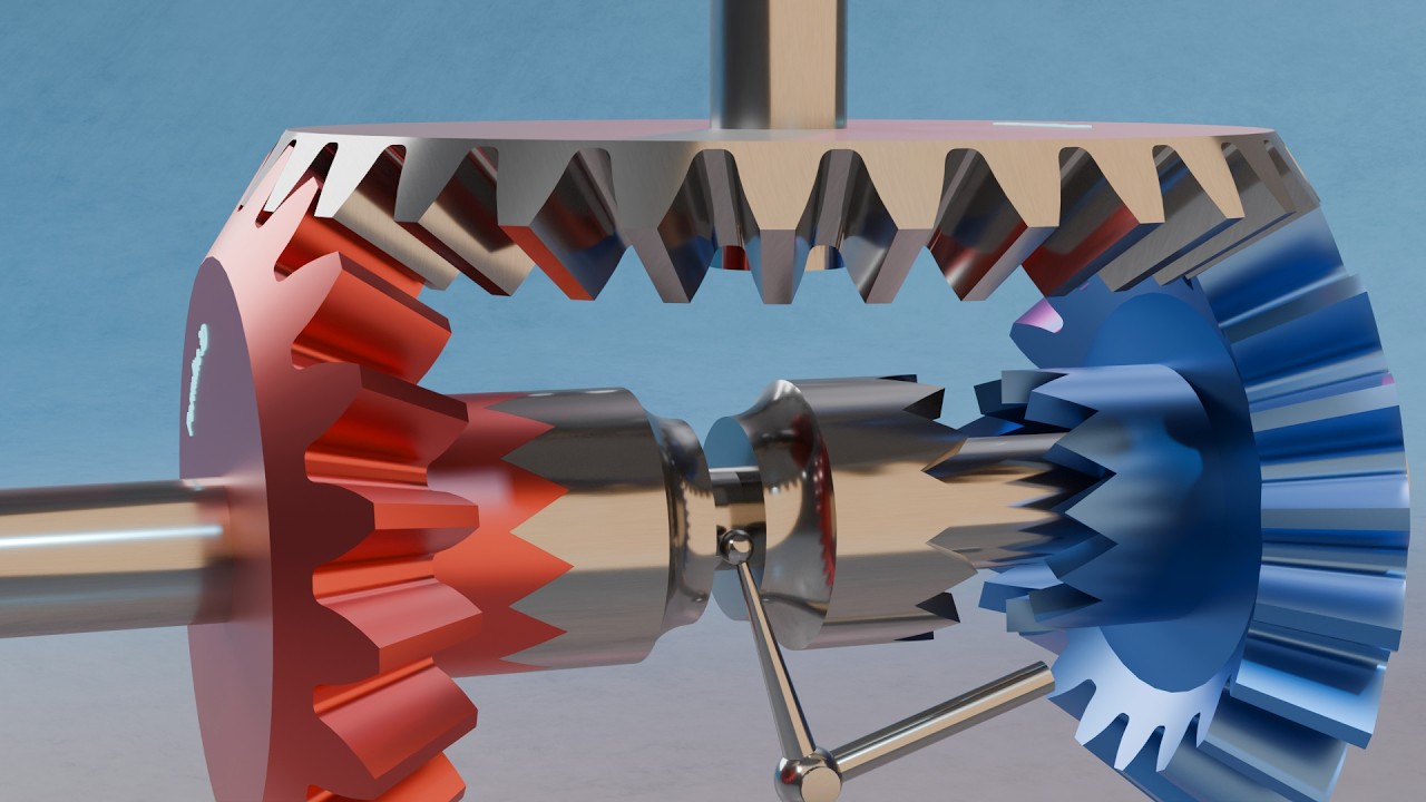
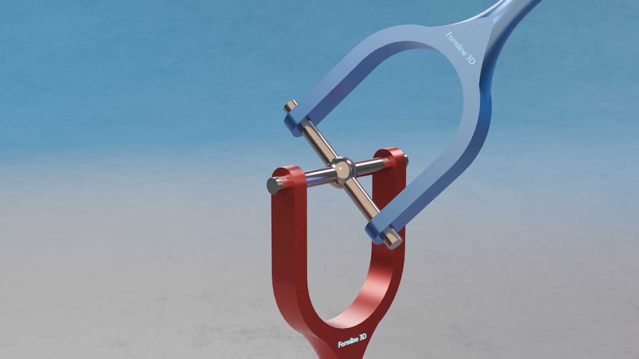
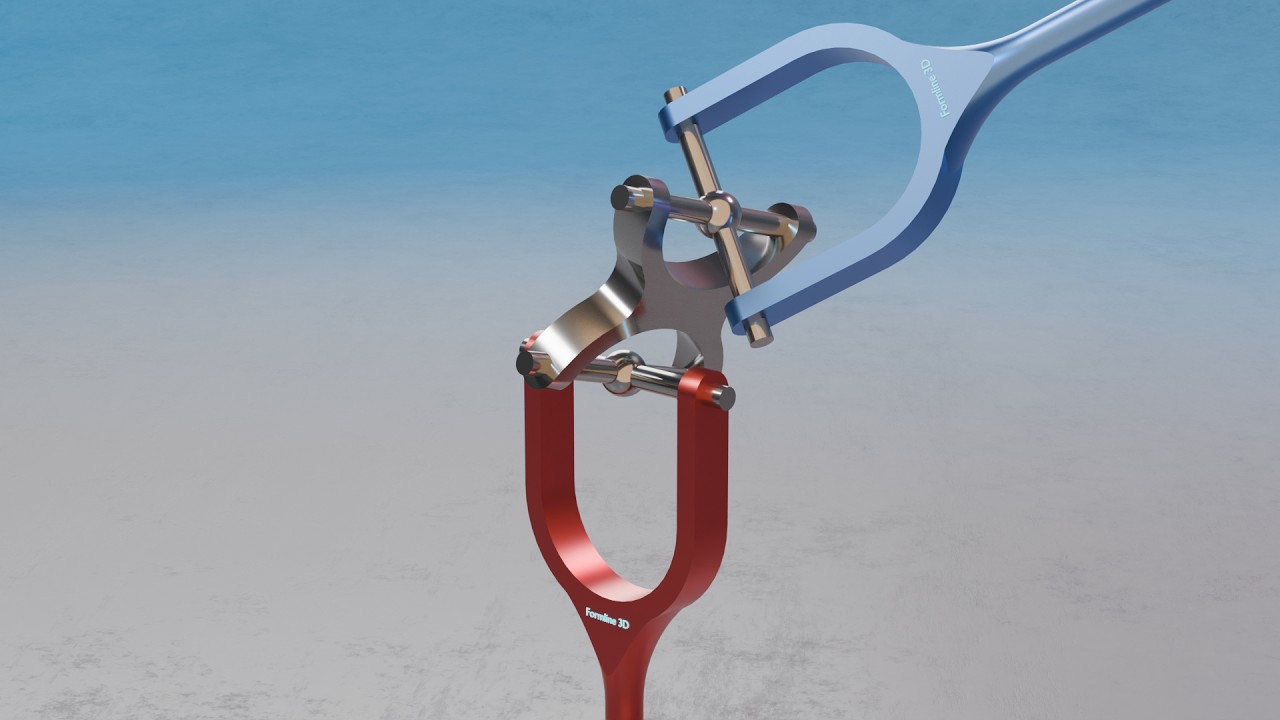
From everyday objects to complex machines, we use Blender and real-time graphics to visualize how things are built, how they work, and how their shapes come together.

No talking heads. No stock footage. Just carefully crafted 3D animations that turn objects, technology, and ideas into clear visual stories.

If you love design, engineering, products, or simply understanding how things are made — you’re in the right place.