Movement No. 145 demonstrates how the reciprocating curvilinear motion of a rocking beam is converted into continuous rotary motion of a crank and flywheel — a configuration central to early steam engine design. The rocking beam pivots about a fixed central fulcrum and traces a curved arc at each end. One end of the beam is connected via a connecting-rod to a crank on the flywheel shaft, converting the arc motion into rotation. The other end of the beam is connected to a lever, one end of which is attached to a small standard that moves with a horizontal reciprocating rectilinear motion — representing the input force from a piston or pump rod. The flywheel stores rotational kinetic energy to smooth out the intermittent impulses from the beam, maintaining steady rotation between power strokes. This arrangement is characteristic of the Watt beam engine and early rotative steam engines that powered the Industrial Revolution.
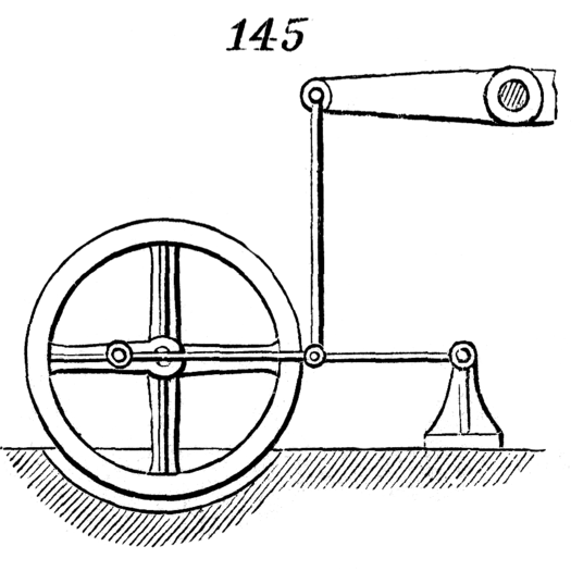
145. Reciprocating curvilinear motion of the beam gives a continuous rotary motion to the crank and fly-wheel. The small standard at the right, to which is attached one end of the lever with which the beam is connected by the connecting-rod, has a horizontal reciprocating rectilinear movement.