Movement No. 62 is a direct and more sophisticated extension of Movement No. 61, introducing the ability to continuously vary the output speed — not just select between two fixed speeds — by replacing the weighted friction-band on the third bevel gear with a fourth pulley actively driven by a separate belt from the upper shaft. The basic architecture is identical to No. 61: three pulleys on the lower shaft (one loose idler, one fast with a bevel gear on its hub, one loose with a transverse bevel gear), plus a third bevel gear interacting with the other two. The crucial difference is that in No. 62, this third bevel gear is now physically attached to a fourth pulley positioned to the right of the other three. This fourth pulley is driven by a separate belt coming from a small pulley on the upper driving shaft — meaning the third bevel gear is no longer passive or friction-held, but actively driven at a controllable speed. The result is a true variable differential drive. When the main left-hand belt engages the middle bevel gear pulley, the differential bevel gear system is active. The output shaft speed now depends on the combination of the main drive and the actively controlled third bevel gear speed. If the fourth pulley’s belt is open (same direction), the third bevel gear’s rotation subtracts from the base double speed — slowing the output. If the fourth pulley’s belt is crossed (opposite direction), the third bevel gear’s rotation adds to the base double speed — increasing the output beyond the base double speed. By varying the speed of the fourth pulley’s drive, or by crossing versus opening its belt, the operator can continuously vary and fine-tune the output shaft speed across a range — making this one of the most sophisticated continuously variable transmission concepts in the entire 507 collection.
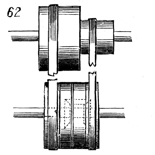
62. For transmitting two speeds, one of which is a different and variable motion. This is very similar to the last, except in the third bevel-gear being attached to a fourth pulley, at the right of the other three, and driven by a band from a small pulley on shaft above. When left-hand belt is on the pulley carrying the middle bevel-gear, and pulley at the right turns in the same direction, the amount of rotation of the third bevel-gear must be deducted from the double speed which the shaft would have if this gear was at rest. If, on the contrary, the right-hand belt be crossed so as to turn the pulley in an opposite direction, that amount must be added.