#067 Tumbler Weight Jumping Motion – 507 Mechanical Movements 3D Animation

#067 Tumbler Weight Jumping Motion – 507 Mechanical Movements 3D Animation

Thursday, Apr 16, 2026

Movement No. 67 presents yet another modification of the jumping intermittent motion concept first introduced in Movement No. 64 — this time using a weight or tumbler E secured directly on the hollow shaft, operating in combination with pin C in the worm-gear shaft. Where No. 64 used a spring and specially shaped cam, and No. 66 used a weighted arm attached to the worm-gear shaft, No. 67 takes a different structural approach: the weight or tumbler E is fixed to the hollow shaft itself — the output shaft that carries the intermittent motion. The worm-gear’s pin C interacts directly with this hollow shaft tumbler. As the worm-gear slowly rotates via the worm drive, its pin C engages the tumbler E on the hollow shaft and carries it along, lifting the weight to a position of unstable equilibrium — past the tipping point. At this critical moment, the tumbler and the hollow shaft are free to fall under gravity independently of the worm-gear, snapping forward rapidly until the weight settles at its new lowest position. The hollow shaft thus receives a sudden rapid rotational impulse — the characteristic jumping motion — before coming to rest and waiting for pin C to catch up and restart the cycle. Compared to No. 66, where the weight arm was fixed to the worm-gear shaft and rotated with it, in No. 67 the tumbler is on the hollow shaft — the driven element — giving the output shaft a more direct and vigorous snap action as the tumbler’s own mass drives the output shaft forward during the falling phase. This series of three modifications (No. 64, 66, and 67) elegantly demonstrates how the same snap-action intermittent principle can be realized through spring-cam, weighted drive-shaft arm, and hollow-shaft tumbler configurations respectively.

@
2 minute read
#066 Weighted Arm Worm Gear Jumping Motion – 507 Mechanical Movements 3D Animation

#066 Weighted Arm Worm Gear Jumping Motion – 507 Mechanical Movements 3D Animation

Wednesday, Apr 15, 2026

Movement No. 66 presents a direct and elegant modification of Movement No. 64 — replacing the spring and cam mechanism of that system with a simpler, gravity-based alternative: a weighted arm. In Movement No. 64, a specially shaped cam and a spring worked together to create the snap-action jumping motion — the spring stored energy as the worm-gear’s pin slowly pushed the cam, then released it suddenly when the cam profile caused the spring’s pressure direction to reverse. In No. 66, this complexity is stripped away entirely. Instead, a weight D is fixed to an arm that is secured to the shaft of the worm-gear. As the worm-gear slowly rotates, the arm and weight rotate with it — gravity acting on the weight creates a torque that, depending on the arm’s angular position, either resists or assists the worm-gear’s rotation. The worm-gear’s pin acts against the arm: when the pin pushes the arm upward past the top dead center position (where gravity transitions from resisting to assisting), the weight and arm drop suddenly under gravity — snapping forward independently of the worm-gear until the pin catches up. This produces the same characteristic jumping snap-action output as No. 64, but driven entirely by the potential energy of gravity stored in the raised weight rather than a compressed spring. The weighted arm solution is simpler and more robust — fewer precision components, no spring fatigue concerns — making it well suited for coarser or higher-duty applications where the spring-and-cam elegance of No. 64 is unnecessary. The modification elegantly demonstrates how the same functional result can be achieved through different energy-storage mechanisms: spring potential energy versus gravitational potential energy.

@
2 minute read
#065 Tappet and Stud Wheel Intermittent Motion – 507 Mechanical Movements 3D Animation

#065 Tappet and Stud Wheel Intermittent Motion – 507 Mechanical Movements 3D Animation

Tuesday, Apr 14, 2026

Movement No. 65 presents a precise and elegant intermittent motion mechanism that advances the driven wheel one stud-space per revolution of the driving wheel — using a tappet, a stud wheel, and a lever-lock stop to ensure controlled, exact single-step indexing. The driving wheel C rotates continuously on the left, carrying tappet A fixed to its face — a projecting element that strikes the studs on the driven wheel. The driven wheel D has a series of equally spaced studs projecting from its face around its circumference. Each complete revolution of wheel C causes tappet A to strike one stud on wheel D, pushing it forward by exactly one stud-space — a precise fractional rotation of wheel D. The critical engineering challenge is preventing wheel D from over-rotating beyond one step — and this is where the lever-like stop comes in. A lever is pivoted on a fixed center between the two wheels. When tappet A strikes a stud on wheel D and pushes it, a notch cut in the periphery of driving wheel C aligns with one end of the lever — allowing that end of the lever to enter the notch and freeing the other end to lock between two studs of wheel D, preventing any further rotation. The instant tappet A finishes pushing the stud and leaves it, the notch on wheel C rotates away — its solid periphery presses on the lever’s free end and forces it back out from between the studs of D. This simultaneously prepares the lever to lock D again at the completion of the next tappet stroke. The result is a perfectly synchronized lock-advance-lock cycle: wheel D advances one precise step per revolution of wheel C, then is positively locked until the next advance.

@
3 minute read
#064 Worm Gear Cam Jumping Motion – 507 Mechanical Movements 3D Animation

#064 Worm Gear Cam Jumping Motion – 507 Mechanical Movements 3D Animation

Monday, Apr 13, 2026

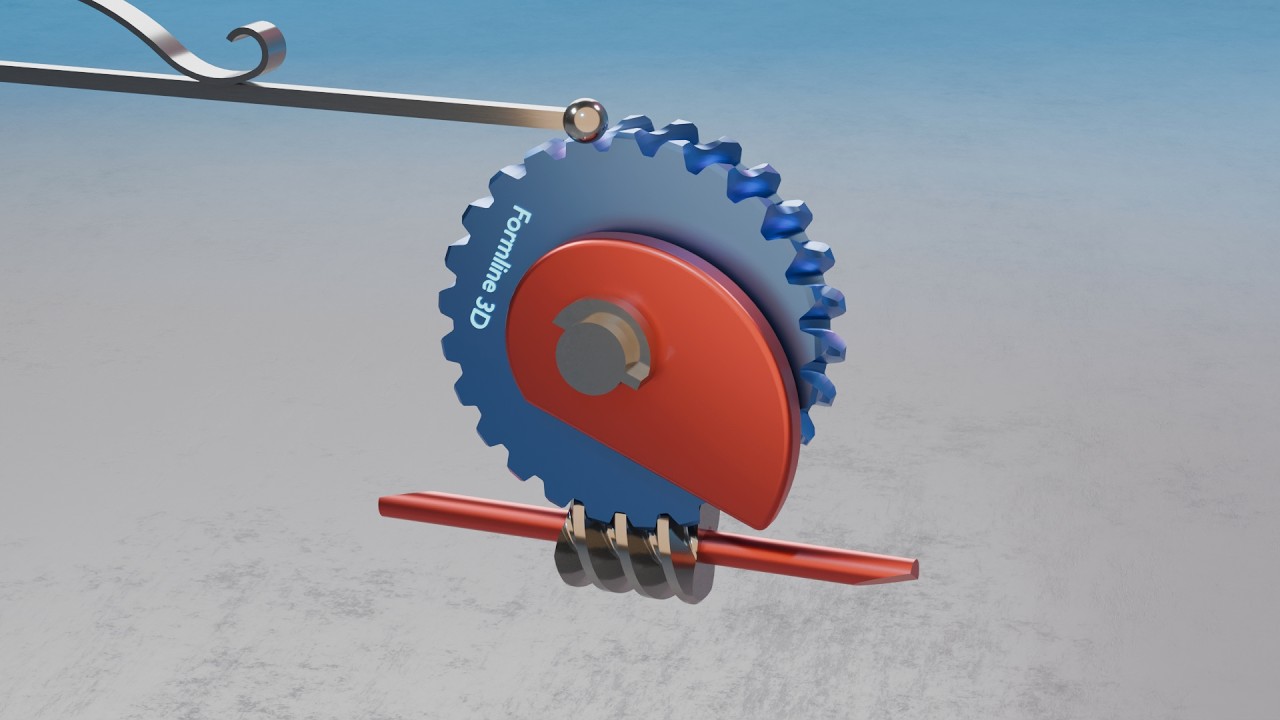
Movement No. 64 presents another ingenious jumping or snap-action intermittent motion mechanism — this time driven by a worm gear and powered by a specially shaped cam and spring combination. The driving shaft at the bottom carries a worm or endless screw that meshes with and continuously drives worm-gear B. Coaxial with the worm-gear shaft is a hollow shaft on which cam A is fixed. A critical detail of this hollow shaft is that a short section of it has been half cut away — creating a notch or recess that interacts with a pin fixed in the worm-gear shaft. The operating principle is as follows: the spring presses continuously against cam A, loading it. As the worm-gear shaft rotates, its pin contacts the notched section of the hollow shaft and pushes the hollow shaft — and with it cam A — along with the worm-gear’s rotation, against the spring pressure. This continues as long as the spring pressure direction keeps the hollow shaft pressed back against the driving pin. However, the peculiar shape of cam A is designed so that as the cam reaches a critical angular position, the direction of the spring’s pressure on the cam suddenly changes — from pushing against the cam’s motion to assisting it. At this tipping point, the cam and hollow shaft are suddenly released from the pin and the spring snaps the cam forward rapidly and independently, while the worm-gear continues its slow steady rotation. The cam snaps to a new resting position and waits there until the worm-gear’s pin catches up to it again, restarting the cycle. This produces a characteristic jumping snap-action output: a period of slow, pin-driven advance followed by a sudden rapid snap, repeating at every worm-gear rotation cycle.

@
2 minute read
#063 Jumping Star Wheel – 507 Mechanical Movements 3D Animation

#063 Jumping Star Wheel – 507 Mechanical Movements 3D Animation

Saturday, Apr 11, 2026

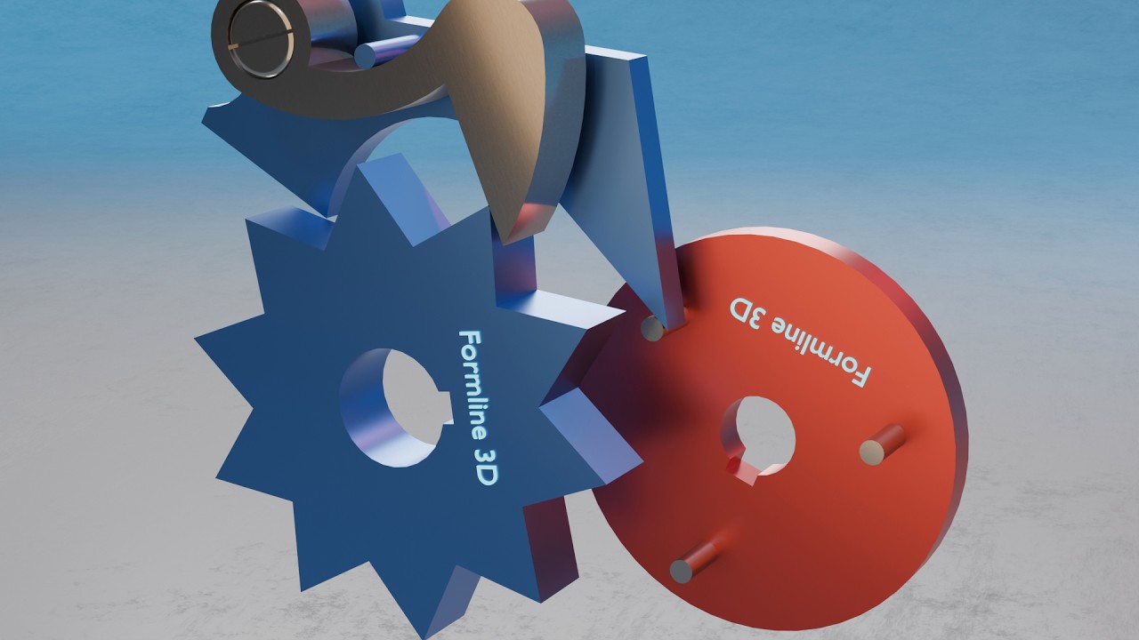
Movement No. 63 presents a beautifully precise intermittent motion mechanism — the jumping star wheel with drop pawl and spring — historically used in meters, revolution counters, and counting devices where a rapid, sharp, and exactly indexed rotary advance is needed once per input cycle. The mechanism has three key components working in sequence. First, a continuously rotating disk on the right carries a series of pins projecting from its face at regular intervals around its circumference. Second, a drop arm is mounted to the left, held up by a spring, with a pawl attached to it that rests in the spaces between the star-wheel’s points. Third, a star-wheel with evenly spaced pointed projections waits to be advanced. The sequence of operation is as follows: as the disk rotates, one of its pins lifts the drop arm — and with it, the attached pawl — upward against the spring force. As the pin continues rotating past the drop arm, the pawl is first released from the pin’s grip and drops into the next space of the star-wheel, positioning itself ready to push. The pin then continues to the drop arm’s catch point and releases it suddenly — the spring violently throws the drop arm downward. The drop arm carries a pin that strikes the pawl, which instantly delivers a sharp, rapid impulse to the star-wheel, advancing it one precise step. The star-wheel then stops and holds its position until the next disk pin repeats the cycle. This snap-action mechanism produces a crisp, well-defined, single-step advance of the star-wheel for each pin on the rotating disk — exactly the sharp, precise indexing needed for reliable digit counting in meters and mechanical counters.

@
2 minute read
#062 Variable Differential Speed Bevel Gear Drive – 507 Mechanical Movements 3D Animation

#062 Variable Differential Speed Bevel Gear Drive – 507 Mechanical Movements 3D Animation

Friday, Apr 10, 2026

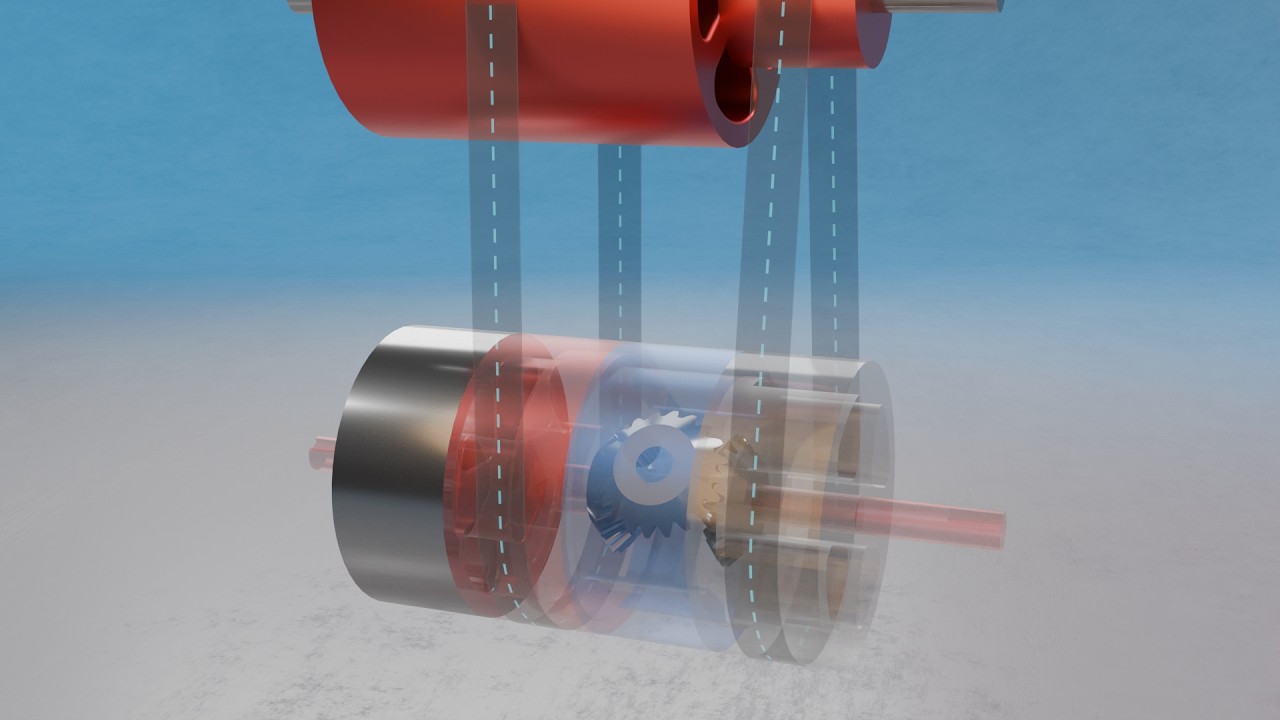
Movement No. 62 is a direct and more sophisticated extension of Movement No. 61, introducing the ability to continuously vary the output speed — not just select between two fixed speeds — by replacing the weighted friction-band on the third bevel gear with a fourth pulley actively driven by a separate belt from the upper shaft. The basic architecture is identical to No. 61: three pulleys on the lower shaft (one loose idler, one fast with a bevel gear on its hub, one loose with a transverse bevel gear), plus a third bevel gear interacting with the other two. The crucial difference is that in No. 62, this third bevel gear is now physically attached to a fourth pulley positioned to the right of the other three. This fourth pulley is driven by a separate belt coming from a small pulley on the upper driving shaft — meaning the third bevel gear is no longer passive or friction-held, but actively driven at a controllable speed. The result is a true variable differential drive. When the main left-hand belt engages the middle bevel gear pulley, the differential bevel gear system is active. The output shaft speed now depends on the combination of the main drive and the actively controlled third bevel gear speed. If the fourth pulley’s belt is open (same direction), the third bevel gear’s rotation subtracts from the base double speed — slowing the output. If the fourth pulley’s belt is crossed (opposite direction), the third bevel gear’s rotation adds to the base double speed — increasing the output beyond the base double speed. By varying the speed of the fourth pulley’s drive, or by crossing versus opening its belt, the operator can continuously vary and fine-tune the output shaft speed across a range — making this one of the most sophisticated continuously variable transmission concepts in the entire 507 collection.

@
3 minute read
#061 Differential Speed Drive with Bevel Gears – 507 Mechanical Movements 3D Animation

#061 Differential Speed Drive with Bevel Gears – 507 Mechanical Movements 3D Animation

Thursday, Apr 9, 2026

Movement No. 61 presents one of the most mechanically sophisticated speed transmission systems in the 507 collection — a two-speed drive that combines belt drive, bevel gearing, and a friction-band braking element to produce both a simple direct speed and a double differential speed from the same input. Three pulleys are arranged on the lower shaft. The leftmost is a loose idler — neutral, transmitting nothing. The middle pulley is fast on the shaft and has a small bevel gear fixed to its hub. The rightmost pulley is also loose on the shaft but carries a transverse bevel gear on its side. A third bevel gear sits loose on the shaft and is held partially stationary by a weighted friction-band — a curb that allows it to slip slightly under sudden speed changes but otherwise holds it. When the belt is placed on the middle fast pulley, the shaft is driven directly and simply at the input belt speed — the bevel gears are not actively engaged in the drive path and the result is a straightforward single speed output. When the belt is shifted to the right-hand loose pulley, the transverse bevel gear on that pulley meshes with the small bevel gear on the fast middle pulley’s hub and also with the third friction-held bevel gear. Because the third bevel gear is held nearly stationary by the friction curb, the rotation of the right pulley’s bevel gear is forced to react against it — and through the differential bevel gear action, the shaft is driven at double the speed compared to the simple mode. The weighted friction-band on the third bevel gear acts as a smooth shock absorber, allowing gradual engagement and preventing sudden mechanical shock when the speed is changed.

@
2 minute read
#060 Two-Speed Double Belt Drive – 507 Mechanical Movements 3D Animation

#060 Two-Speed Double Belt Drive – 507 Mechanical Movements 3D Animation

Wednesday, Apr 8, 2026

Movement No. 60 presents an elegant two-speed transmission system that uses two drive belts and a carefully arranged set of four pulleys to select between two distinct output speeds on the lower shaft — without any gears, clutches, or complex mechanisms. The lower output shaft carries four pulleys mounted side by side. The two outer pulleys are loose — they spin freely on the shaft and transmit no motion to it. The two inner pulleys are fast — they are keyed or fixed to the shaft and rotate with it as a rigid unit. Two drive belts connect the upper driving shaft to the lower output shaft — each belt running over one upper pulley and one of the lower four. The upper pulleys are of different diameters, giving each belt a different speed ratio when engaged. The speed selection works by shifting both belts simultaneously. In the first state — slow speed — the right-hand belt rides on its fast (inner) lower pulley, driving the shaft, while the left-hand belt rides on its loose (outer) lower pulley, freewheeling without driving. Only the right belt is actively transmitting, and the pulley-size ratio it engages produces the slower output speed. To switch to fast speed, both belts are shifted simultaneously: the right belt moves to its loose outer pulley (disengaging), and the left belt moves to its fast inner pulley (engaging). Now the left belt drives the shaft through a different pulley ratio, producing the faster output speed. This two-belt, four-pulley arrangement cleverly ensures that exactly one belt is always driving while the other freewheels — providing a seamless, continuous speed selection without interrupting the drive. The mechanism is a direct application of the fast-and-loose pulley principle that was fundamental to 19th-century mill and factory line-shaft systems.

@
2 minute read
#059 Two-Speed Belt and Gear Transmission – 507 Mechanical Movements 3D Animation

#059 Two-Speed Belt and Gear Transmission – 507 Mechanical Movements 3D Animation

Tuesday, Apr 7, 2026

Movement No. 59 presents a compact and practical two-speed gear transmission system that uses a combination of belt drive and spur gearing to deliver two selectable output speeds to a lower shaft — plus a neutral disengaged state — by shifting a single drive belt across three pulleys. The three pulleys are arranged side by side on the input side. The leftmost pulley is a loose idler — when the belt rides here, no power is transmitted to any gear, placing the system in neutral. The middle pulley is fixed directly to the shaft of a small pinion gear. When the belt is placed on this middle pulley, the small pinion is driven and meshes with the output gear on the lower shaft — because the pinion is small relative to the output gear, this produces a slow output speed with high torque, as the large gear ratio reduces the speed significantly. The rightmost pulley is fixed to a hollow shaft that runs concentrically around the pinion shaft — independently of it — with a large spur gear fixed to its far end. When the belt is shifted to this rightmost pulley, the hollow shaft and its large spur gear are driven instead. Since the large spur gear is bigger than the small pinion, it meshes with the output gear at a more favorable ratio, producing a faster output speed proportional to the diameter difference between the two input gears. This elegant two-speed arrangement — neutral, slow, and fast — is directly related to Movement No. 58’s three-speed system, but simplified to two active speeds using one solid shaft and one hollow shaft, making it ideal for simpler machine tools and light industrial equipment requiring basic two-speed operation.

@
2 minute read
#058 Three-Speed Concentric Shaft Gear Transmission – 507 Mechanical Movements 3D Animation

#058 Three-Speed Concentric Shaft Gear Transmission – 507 Mechanical Movements 3D Animation

Monday, Apr 6, 2026

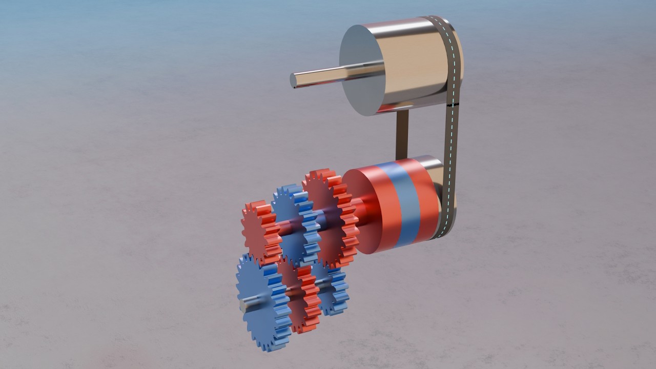
Movement No. 58 presents a highly ingenious multi-speed transmission system that delivers three distinct output speeds to a lower shaft using a clever arrangement of concentric hollow shafts, multiple pulleys, and spur gears of different sizes — all selectable by shifting a single drive belt. The input side consists of four pulleys mounted side by side. The first is a loose idler pulley — when the belt rides here, no motion is transmitted at all, giving a neutral state. The second pulley is fixed directly to the solid main shaft, which carries a small spur gear on its opposite end. The third pulley is fixed to a hollow shaft that runs concentrically over the main shaft — independent of it — and carries a second, larger spur gear on its other end. The fourth pulley is fixed to yet another hollow shaft that runs concentrically over the previous hollow shaft, also independent, carrying an even larger spur gear at its other end. All three spur gears of different sizes mesh with a common gear on the lower output shaft. When the belt is placed on pulley two, the main shaft and its small spur gear are driven — producing the highest output speed on the lower shaft due to the small gear ratio. When shifted to pulley three, the first hollow shaft and its medium spur gear are driven — producing an intermediate output speed. When shifted to pulley four, the outer hollow shaft and its large spur gear are driven — producing the lowest output speed with the highest torque. This elegant system of nested concentric shafts allows three completely independent speed ratios to be selected by a single belt shift, without requiring any gear-shifting mechanism — a remarkable feat of compact mechanical design used in machine tools and early industrial equipment.

@
2 minute read

© 2026 Formline 3D Mechanisms

Powered by Formline 3D

Formline 3D

Formline 3D is a 3D animation channel exploring the form, structure, and design of the world around us.

From everyday objects to complex machines, we use Blender and real-time graphics to visualize how things are built, how they work, and how their shapes come together.

No talking heads. No stock footage. Just carefully crafted 3D animations that turn objects, technology, and ideas into clear visual stories.

If you love design, engineering, products, or simply understanding how things are made — you’re in the right place.